Weld ring gaskets
Weld ring gaskets are used in the most critical flange connections where a welded seal is required—typically due to the hazardous nature of the medium or the risk posed by loss of functionality. While the connection must offer extreme sealing performance and safety, it also needs to be detachable to… Read more
Product description
Weld ring gaskets are used in the most critical flange connections where a welded seal is required—typically due to the hazardous nature of the medium or the risk posed by loss of functionality. While the connection must offer extreme sealing performance and safety, it also needs to be detachable to some degree. In such cases, a weld ring gasket is an optimal solution: the connection can be disassembled, but it requires cutting the weld as well as unbolting the flanges—thus, the gasket is considered semidetachable.
Welded flange joints meet the highest sealing requirements and are mandatory particularly when process conditions or the conveyed medium are exceptionally dangerous. Weld ring gaskets are generally made from the same or a compatible material as the pipe or flange, and they are always used in pairs.
Each weld ring gasket consists of two halves: one half is first welded to each flange side, and then the two halves are welded together to form the final seal.
Profiles and Weld Seams
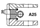
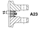
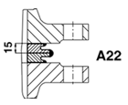
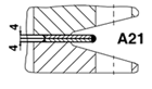
The selection between different weld ring profiles depends on the operating conditions—such as pressure, temperature, and mechanical stress. Profiles A21 to A25 represent the most common shapes, and their typical features are presented in a separate table.
- The attachment seam refers to the weld joint between a gasket half and the flange. Depending on the gasket type, the attachment seam may be internal, external, or both.
- The seal seam always refers to the weld between the two gasket halves, ensuring a tight and secure connection.
| Profile | Internal “attachment seam” Crevice corrosion between weld ring and flange is avoided | External “attachment seam” Re-welding or disassembly possible | Capacity of radial differential expansion | Undo and re-weld |
|---|---|---|---|---|
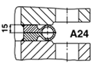 | Usual | Not possible | Depending on the thickness of the wall of the torus, to a max. ∆ r ~ 5 mm | Easy to separate with a 2 mm cutting wheel. Can be re-welded 2 to 4 times |
 | Possible to have additional attachment. Intermittently welded | Usual | Depending on the thickness of the wall of the torus, to a max. ∆ r ~ 5 mm | Easy to separate with a 2 mm cutting wheel. Can be re-welded 2 to 4 times |
 | Only as an additional attachment. Intermittently welded if there is a danger | Usual setup – Only as an additional attachment aid. Intermittently welded of corrosion | Only low capacity due to the small lip. max. ∆ r ~ 0,5 mm | Difficult to separate. Can be re-welded 1 to 3 times |
 | Only as an additional attachment. Intermittently welded if there is a danger | Usual setup – Only as an additional attachment aid. Intermittently welded of corrosion | Not really possible. max.. ∆ r ~ 0,1 mm | With cutting wheel Separation loss 2 to 3 mm respectively. Can be re-welded of corrosion 3 to 5 times |
 | Usual | Not possible Flange form M in accordance with DIN 2526 also | Modest capacity Depending on projection max.. ∆ r ~ 0,3 mm | With cutting wheel Separation loss 2 to 3 mm respectively. Can be necessary re-welded 2 to 4 times |